
Formula SAE
My time as a member of the Illini Formula SAE team provided me with valuable hands-on automotive experience, along with involvement in research and design (R&D) projects. The team was divided into ‘subsystems’, of which I was primarily involved in chassis; with some additional involvement in aerodynamics and suspension. The following sections detail three of my main projects across the 2020 and 2021 seasons:
— The 2020 Car —
Impact Attenuator
One of the first thing I did for the chassis subsystem was the accurate installation of an impact attenuator plate, which is intended to absorb energy in the event of a front end impact. The impact attenuator itself was an aluminum honeycomb structure, with the mounting plate being made of stainless steel. The attenuator needed to be perfectly centered on the plate, and these collectively needed to mount flush with the front section of the car. This would all eventually fit within a ‘nose’ cone for improved aerodynamics.


Following the completion of the impact attenuator plate, I completed some work for the aerodynamics subsystem. My task was to prepare molds for the production of the rear diffuser and diffuser louvers. This was particularly interesting to me since I was able to assist in the production of carbon fiber parts and got more familiar with the more general process of producing parts from a mold.
Then, as the ‘driving car’ deadline approached, I worked with the suspension sub-system in the disassembly and reassembly of both front and rear suspension systems. This was necessary to replace certain screws at points of perpendicular load such that FSAE regulations were met. The replacement screws additionally reduced weight slightly because many of the original/old screws were needlessly long.

Front ‘A-Arm’ Suspension & Brakes Assembly (2020)
— The 2021 Car —
Electronic Shift Actuator
One of my projects for the 2021 car was the selection and implementation of an electronic shift actuator. Since the FSAE car uses an engine and transmission sourced from Yamaha’s R6, it too has a sequential gearbox. The purpose of this component was to allow the driver to use paddle shifters from the steering wheel to control the vehicle’s gear selection.
Our team had previously been using an electronic actuator produced by Kliktronic to achieve this. However, the car was experiencing trouble shifting into second gear. A new actuator had been proposed as a potential solution and I was tasked with selecting a new product. In researching potential alternatives for the existing actuator, a lightweight build, electronic actuation and compatibility with the engine were the main considerations.
However, based on a quantitative comparison there were very minimal differences between the Kliktronic actuator and competing products. So, seeing as other actuators offered little to no benefit in applied force or reduced weight, I proposed that the solution to the shifting problems would more likely be found by reevaluating the way the team’s existing actuator was mounted.


Prior to designing a new mount, I first got some hands-on experience mounting the Kliktronic actuator onto the 2021 car (shown above). Kliktronic's installation guide gave me some good insight as to the ideal mounting of the actuator. Particularly, the actuator is usually best mounted such that the rod is 90 degrees relative to the shift arm. In this position, a 25mm stroke from the actuating rod should engage a shift. Knowing these guidelines, I was able to properly install the actuator. The success of this installation was established the following weekend when the former low-end shifting issues were resolved. Since this alignment worked well, I took measurements of the shift angles and other relevant details:
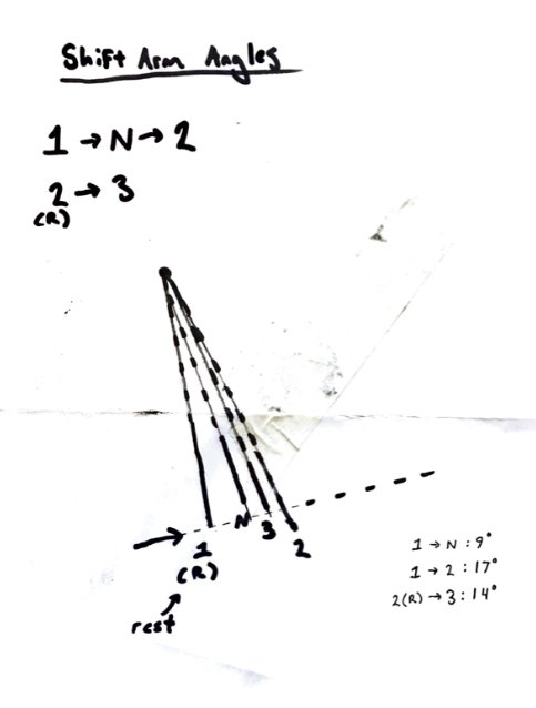
Shift linkage positional measurements

Table of shift linkage measurements
I took measurements for the shift angle by taping the paper shown above to the engine, and tracing the position of the shift arm for each gear shift. As shown, the actuation distance from the ‘rest’ position is shorter by 5mm for gears 3+ than it is for 1 -> 2. These measurements are very close to Kliktronic’s recommendations, as the angle between the shift rod and arm at the rest position was measured to be 91 degrees, and actuation from first to second gear occurred at 26mm of extension.
Having found an ideal mounting position for the actuator, the next step was to begin designing a mount. There were limited options for mounting points on the car due to space constrictions near the engine, thus a nearby chassis tube was identified as the most feasible option. To create a firm fitment, I designed this to mount to the chassis tubing with a bolt (as seen in the drawing below). The angle between the tube and the engine was negated via an angled mounting plate. Additionally, a bearing was necessary at the joint between the actuator and mounting plate, allowing the actuator to rotate slightly while shifting (better applying the actuator’s linear motion to the shift linkage’s rotational path).


Steering Column - Adjustable Mounting Jig
The goal of this project was to design a jig that could hold the steering column in a fixed position for testing and assembly. This was important in order to customize the vehicle’s ergonomic feel for the intended driver. Thus, to be most effective, the jig needed the ability for controlled movement of the steering assembly such that any adjustments can be made prior to permanent modifications (i.e., welding a fixed steering column support).


Shown below is my initial design concept for the steering jig. To minimize time-intensive manufacturing, I selected some parts that could be sourced; particularly the threaded rods and bolts as well as standard bearings. This design allows for manual adjustment of the steering column angle through the use of a wrench. Additionally, the baseplate of this jig can be mounted directly into the pre-existing mounting points used by the permanent steering column support (shown above).
My design saw various changes throughout the semester (initial and final designs shown below).


In the end, the jig achieved the initially prescribed goals, and gained new features with later versions; such as a built-in tool for measuring the angle of the steering column relative to the top of the monocoque. This was done through the use of concentric discs with ‘top dead center’ indications.